


Radar Level Gauge:
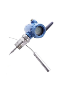
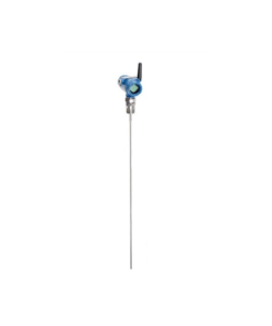
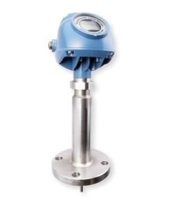
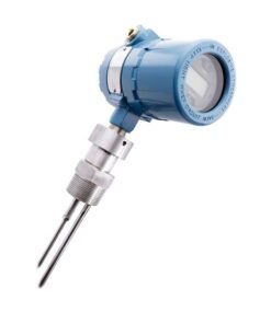
The radar level gauge is a highly reliable non-contact instrument used for measuring levels. It utilizes radar waves that can penetrate foam, smoke, and steam, providing accurate measurements unaffected by changing environmental conditions. Due to its capabilities, radar level gauges have found wide applications in the refining industry. The Rosemount 5400 series radar level gauge incorporates radar pulse wave technology, low power consumption, a two-wire 24VDC power supply, intrinsic safety, and high accuracy, making it a commonly used solution in our company.
Working Principle of Radar Level Gauge:
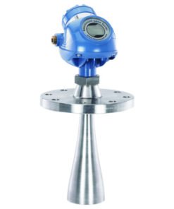
The radar level gauge emits microwaves through an antenna towards the measured medium’s level. It measures the time taken for the microwaves to be emitted and reflected back, enabling the determination of the liquid level inside the container. The 5400 series radar level gauge includes two models: 5401 [6 GHz], a low-frequency transmitter suitable for turbulent, steam-heavy, or foam-prone environments, and 5402 [26 GHz], a high-frequency transmitter with a narrow radar beam width suitable for devices with higher or narrower nozzles.
Parameter Settings for 5400 Series Radar Level Gauge:
The basic configuration of the 5400 series radar level gauge can be performed using the Rosemount radar host software (RadarMaster), field communicators, AMSTM kits, or DeltaV. As instrument maintenance personnel, we commonly set parameters using a field communicator, focusing on important parameters such as Tank Height, Range Values, Upper Null Zone, and Set Threshold. Accurate parameter settings are crucial for obtaining reliable measurement results. The radar’s output during a fault state can be defined by configuring the alarm mode (Alarm Mode). Additionally, the Loop Test function plays a significant role in circuit debugging before operation.
Process Variables:
Under the process variable menu, various diagnostics and maintenance options are available, including restoring instrument parameters to factory settings (Factory Setting), restarting the instrument (Restart Device), and performing loop testing, diagnostics, and simulation.
Basic Setup:
① The length unit can be configured and set in the Measurement Unit.
② Tank setup allows configuring the Tank Type, Tank Bottom Type, and Tank Height.
③ AO settings involve configuring range values, alarm mode, and PV. Additionally, damping values are configured under the basic settings menu.
Common Fault Analysis of 5400 Series Radar Level Gauge:
Issue: Output value of the radar level gauge reaches maximum.
Cause analysis: This issue commonly occurs due to water droplets or dirt beneath the radar level gauge’s transmission antenna or isolation window.
Troubleshooting: Remove the liquid level gauge and use a clean, soft cotton cloth to dry any water droplets or dirt beneath the antenna or isolation window. After restarting the gauge, it should return to normal. It’s important to clean the transmission antenna using a silk or soft cotton cloth dipped in alcohol, gasoline, or other solvents, avoiding alkaline solvents.
Issue: Frequent automatic restart of the radar level gauge.
Cause analysis: The radar level gauge restarts suddenly during operation when connected to the Emerson DCS, powered by a two-wire AI card. The display window goes black and shows the restarting process. After restart, the display window shows the measured liquid level, followed by a high liquid level alarm after 3-5 seconds, and the display window goes black again. This process repeats. Initial suspicion is on the gauge, but after replacing it with a new one and encountering the same issue, it’s determined that the instrument is not at fault. Detailed inspection reveals an undamaged signal circuit, proper grounding, normal shaking table detection, and a measured output voltage of around DC23.8V from the AI card. The radar level gauge works normally when directly connected to the control room. During the restart process, it is discovered that the instrument’s power supply drops to around DC15V during the high-level alarm, below the minimum required DC16V for normal operation. The installation distance of the gauge from the DCS cabinet is approximately 100m, leading to the conclusion that insufficient load capacity of the DCS two-wire AI card is the cause.
Troubleshooting: Connect the DC24V power supply and radar level gauge in series to the DCS four-wire AI circuit. Following this improvement, the frequent restart issue of the radar level gauge has been completely resolved after nearly half a year of observation and use.


Reviews
There are no reviews yet.